Reef Discussion

Str8edge

Member
Mar 10, 2013
213
97
Shepparton
Help with stingray ro/di filter set up
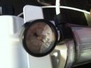
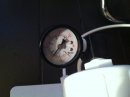
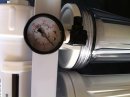
Hey guys I have just purchased my first ro/di filter from the reef shop and need help with a couple of connections the instructions that came with it are about as helpful as sand paper for toilet paper. The unit is a stingray as per pic 1.. My first question is the water feed going into the unit I'm assuming goes in the connection with the pressure gauge as per pic
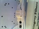
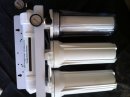
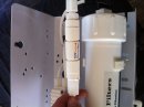
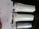
2.. The waste water from the membrane comes out of the pressure restricted connection? As per pic 3.. And the final connection point is behind one of the filters as per pic 4 I'm assuming if all my connections are correct this is the ro/di water for the tank..
If anyone knows this unit or knows if the connections are correct please comment so that I can start this monster up and collect water..
Thanks in advance..
 

Attachments

rockerpeller

Member
Oct 14, 2011
1,261
436
Hastings, Vic
I have the same unit and came across the same problems.
1. That's the filtered water outlet. The clear housing is the di housing.
2. You're right in thinking that's the waste water.
3. That would be the water inlet from the tap.

I didn't really want to rely on the gauges, so i added a dual inline TDS meter.
 

Str8edge

Member
Mar 10, 2013
213
97
Shepparton
Ok cool thanks for that.. How do you find the unit it was quite cheap so I hope it does the job.. With the membrane when placing inside its chamber it's has like a flange a thicker part to the membrane I assume this goes to the outlet end in the chamber which would leave the tap looking connection to the inlet side.. Sorry about all the questions..
 

rockerpeller

Member
Oct 14, 2011
1,261
436
Hastings, Vic
it takes awhile to get 0 on the tds. Usually around 30 mins, but it fills a 20l container in around 20 mins, so its not so bad.
There's only one way that the membrane will fit from memory.

I think I'll go for a @VaultBoy special for my next filter.
 

VaultBoy

Member
Jul 10, 2011
2,279
673
Gawler, S.A.
As you look at the unit front on the housing on the top of the bracket is the membrane housing. The bottom left housing is should be sediment this is the first filter in the line the middle housing should be carbon or carbon/sediment this is the second filter the membrane is the fourth and the right is the DI resin housing is the fourth "filter". The membrane should only fit one way. If it has a rubber seal around the outside of the membrane then that end goes in last. The valve you are holding in the third pic is the flow restrictor which goes to the drain. This valve controls how much water is rejected by the membrane and hence controls the production rate and quality of the permeate.

Your tap water should go into the first filter (bottom left) and your waste water goes to the drain. There looks to be 2 outlets one on the outlet of the membrane housing this would be for connecting to a storage tank and to a drinking water tap possible through a post carbon filter or mineraliser and the other outlet is the one on the DI housing this is the final, polished, product water that you would add to your tank.

Without knowing what membrane you have its hard to say what sort of production times but mine takes about an hour to produce 10 - 12 litres of water with the water storage tank connected. With the tank connected I can draw off about 15 litres in about 10 mins but then slows to a dribble and takes time to fill the tank again.

Do you have a TDS meter? It is the only real way to measure the quality of the water produced. You are possibly better off getting a hand held Electrical Conductivity meter which is simply a more accurate TDS meter if you can get them for roughly the same price.
 

Str8edge

Member
Mar 10, 2013
213
97
Shepparton
Ok guys thanks for that.. I have hooked it all up as described I only have one more question as I have started to fill the unit up it was running for roughly 10 mins but no water has made it to the membrane chamber yet is this normal or is there a blockage of some sort.. There is definitely water going into the first chamber is it was under pressure when I disconnected it.. Lets just say I'm wet and the laundry walls got a wash.. :)
 

rockerpeller

Member
Oct 14, 2011
1,261
436
Hastings, Vic
I don't remember my start procedure but check all the housings to make sure there isn't anything wrapped up. I left my unit running for close to an hour, before i went back to check it.

edit: let me know what you're gauges say. Mine sit around the 85psi mark
 

Str8edge

Member
Mar 10, 2013
213
97
Shepparton
That was a complete pain in the ass.. The box on the top which I think is like a one way valve (see photo) I think was all connected back to front from the factory that's why I couldn't get water into the 2nd chamber.. The way it was connected was first chamber straight into the reverse end of the ro membrane then down to the 2nd chamber in the then to the 3rd and final chamber.. I transferred them all over and started getting waste water straight away so know it goes water into the sediment chamber then to carbon, to membrane to final de-ionization chamber out through pressure gauge comes the ro/di chamber.. I may have the water in and the water out around the wrong way in the last chamber as the pressure gauge is reading zero I'm unsure on that @rockerpeller does your ro water come out through the front of the last (clear) chamber or out the back?? See photos below

sorry @rockerpeller just re read your first post and your ro water comes out the front im unsure on the use of the pressure gauge here then as the water will just flow out the hose and wont build up any pressure...
 

Attachments

rockerpeller

Member
Oct 14, 2011
1,261
436
Hastings, Vic
Crap i need to make a correction. Reverse the order entirely. It goes in this order; tap - clear housing - middle - tube on top - left housing - filtered water out let.
I should have mentioned, i swapped the 1st and last housings around.
So sorry for the stuff around mate. I pulled my filter off the wall to confirm the sequence, and that's the order above.
 

Str8edge

Member
Mar 10, 2013
213
97
Shepparton
haha poop..
that makes more sense with the other pressure gauge now.. that means the way the factory had it set up must have been right.. no stress mate i shall fix i might just swap the first and last chamber around and change the inlet..
 

VaultBoy

Member
Jul 10, 2011
2,279
673
Gawler, S.A.
So I just drew you a little pic...

ro system diagram.png


The 4way valve is actually an automatic shut off valve. One side should be marked "tank" or similar and this is the outlet side of the valve.

The diagram shows a 1 way valve but this may be built into the membrane housing or the fitting coming out of it and hence may not be immediately apparent.

Most of the parts (housings valves etc.) should have arrows on them indicating flow directions if you look carefully. Let me know if you need any more help.
 

WayneS

Member
Jun 23, 2021
1
0
I am new to reefing, having Just purchased my first tank and complete system second hand.

The system includes a StingRay RO/DI filter as discussed above.

I was able to make around 180 litres of RO/DI water, but now I have no flow only waste water.
Any ideas what might now be stopping the flow of RODI water?

1. Could one or more of the filters be blocked?
2. If filters need replacing, please advise recommended sources for replacement filters. Prefer Australian suppliers as I live in Sydney. I do have a new bag of DI resin.

Thanks in advance,
Cheers
Wayne